ChrisofMaine
-
Posts
764 -
Joined
-
Last visited
Never
Content Type
Profiles
Gallery
Everything posted by ChrisofMaine
-
From the album: Chapman
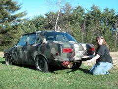
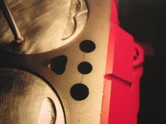
The infamous Per-Ka Tip, modeled by Chris Of Maine's four door and presented by Alisha "Vanna" Saulnier. -
From the album: Chapman
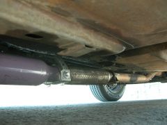
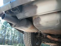
Rear view of the header flange. The header glasspak tucks up nicely due to the the Experimental Engineering tranny crossmember. -
From the album: Chapman
This is the back of glaspack into the flextube. I added a hangar attached to the tunnel to support the rear of the glaspack. The 2" pipe through the crossmember has been on the car since I bought it in 1990... -
From the album: Chapman
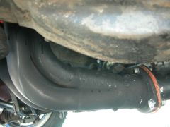
This is the Comp header with the welded on flange. It took a few test fits to get the angle correct for the header muffler to fit well. You can see the Pan-Evac port just to the left of the flange, and the O2 sensor just to the right of the flange. The O2 sensor bung is welded into the header muffler. -
From the album: Chapman
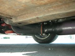
This is the same Flowmaster I had on the old Junkbox wagon. It is a tight fit, but it tucks into the stock location well. -
From the album: Chapman
Nissan Comp Header, with a welded flange, Purple Hornie header muffler, flex joint, 2" intermediate pipe, 2 chamber Flowmaster with an 8" straight tip. -
From the album: Chapman
Nissan Comp Header, with a welded flange, Purple Hornie header muffler, flex joint, 2" intermediate pipe, 2 chamber Flowmaster with an 8" straight tip. -
From the album: Chapman
Nissan Comp Header, with a welded flange, Purple Hornie header muffler, flex joint, 2" intermediate pipe, 2 chamber Flowmaster with an 8" straight tip. -
-
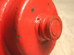 This is a close up of the pulley and shaft. The inner race of the clutch fan bearing can be seen still attached to the shaft.
 -
From the album: LZ22 Engine Stuff
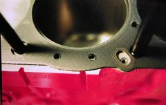
This shot shows the block with the gasket sitting on it. You can see the oil passage offset for the head as well as added holes in the NAPZ24 head gasket for steam holes added to the block and gasket for the L head. Using the NISMO gasket eliminates the need to add holes to the gasket. The oil feed hole in the head is located at the other side of the slot in the gasket. You can use a die grinder to elongate the oil feed hole in the head to match the slot on the gasket. -
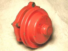 This shot shows a Nissan Clutch fan water pump with the clutch fan part cut off. The pully is factory welded to the stub shaft.
 -
From the album: LZ22 Engine Stuff
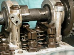
This is the place where NAPZ 22 and 24 blocks are known to crack. It is on the exhaust side of the block, between cylinders 2 & 3. The crack goes from the head bolt hole across to two water coolant passages. -
Various photos of my now deceased '71 "Junkbox" 510 Wagon
-
-
From the album: Junkbox Gallery
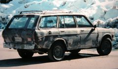
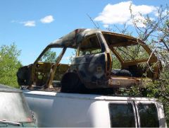
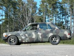
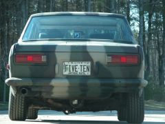
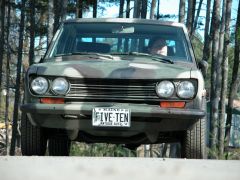
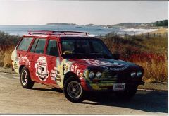
Back in 1996, the Junkbox started its Chris of Maine life as the PirateMobile. It was painted in the colors of the local Portland AHL franchise, the Portland Pirates. -
 Merry Christmas to all!!!!
 -
From the album: Chapman
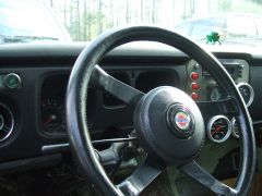
Momo wheel using modified Z-car hub & pad, with modified Grant horn button. -
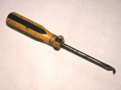 I made this by filing an old flat screwdriver tip.
 -
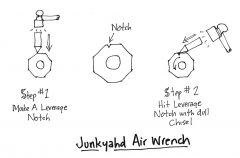 Method for removing large nuts (strut gland, axel shaft, etc.) without conventional tools or compressed air.
 -
From the album: Chapman
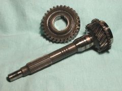
Truck input gear(22 teeth) / countershaft gear (31 teeth). This set has four grooves around the input shaft. Here is a picture of what the grooves look like, and the removed countershaft gear. -
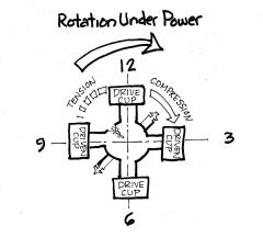 The grease nipples should be located on the compression side of the ujoint. It they are on the tension side, the ujoint cross is weaker in application. Look at it like this: Pretend you have the car on a lift, and you are looking at the differential from the passenger's side rear wheel opening. Hold the ujoint up with the cups at 12, 3, 6, and 9. Imagine that cups 12 and 6 are connected to the differential yoke. These are the "drive cups" Cups 3 and 9 are connected to the halfshaft itself, these are the driven cups. In this position, the grease nipple should be at the 1:30 or 7:30 position. That puts it in compression. It should not be in the 4:30 or 10:30 position, or in tension. This rule holds true for all ujoints, place the nipple after the drive cup, not before the drive cup. Probably overkill for a street driven car, but the correct way to do it. Also pack the joints manually as well as possible during assembly, don't just put them in then count on the grease nipple to give you full coverage.
 -
From the album: LZ22 Engine Stuff
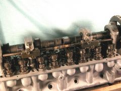
This is a detail shot of the cam tower for the mounting of the internal spray bar. The hole to the lower right is the oil feed hole. At this stage of head assembly, the rockers were just being installed, that is why the pivot posts are fully down. -
From the album: LZ22 Engine Stuff
This shows the sectioned spraybar mounted to the cam towers. In the middle, you can see the brazed sleeve over the butt junction. -
Derek - ready to work on his 510
ChrisofMaine commented on derek's gallery image in Member Galleries
 LOL.... eeeexxxcelllent!!!
 -
From the album: LZ22 Engine Stuff
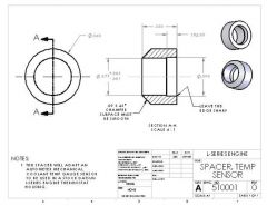
This is a drawing for the temp sender bushing if you want to have it machined up.