paolo
-
Posts
97 -
Joined
-
Last visited
-
Days Won
1
1 Follower

paolo's Achievements
")


-
Useful DATA you can see for FREE!
-
-
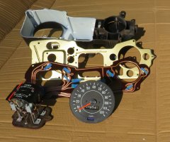
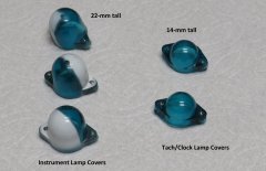 Image tells all. This explains why short profile 'bulbs' or LEDs are needed for the factory tachometer or clock.
 -
Images of various parts or states of my instrument cluster (dash pod) rebuilds and rebuilding processes.
-
-
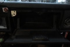
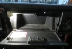 Installed and operating. Turns on when lights (markers+) are turned on and box door is opened. Intentionally not painted black as reminder for prototype model. Image taken near end of 'civil' twilight.
 -
A simple custom built glove box lamp made from readily available parts.
-
-
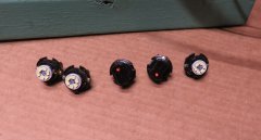
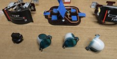
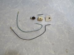 Glove box lamp parts. 1 - Outer frame (flat piece) from a a cut-out bit of 1/10" plastic of an old computer or electronic widget. 2- Pipe is cut from 3/4" CPVC pipe. 3 - Switch is a normally closed (NC) push-button available for cheap on-line by the 10-pack. 4 - Wires are color matched parts from an old harness with coordinated barrel connectors from VintageConnections.com 5 - LED another online Amazon part. 6 - Socket is typical lamp socket from Datsun 510 instrument cluster panel which fits snugly into pipe. All assembled with hot glue. Paint as desired. Contact me for part sources.
 -
'Exploded' assembly of parts (less bulb).
-
-
 paolo changed their profile photo
 -
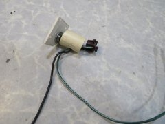
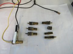
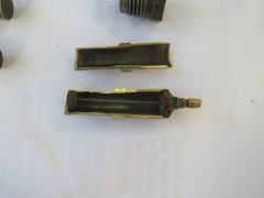 A sectioned Datsun thermistor, just in case you're curious as to how they are built.
 -
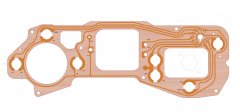
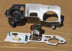 White paint job for housing and metal support panel exposed.
 -
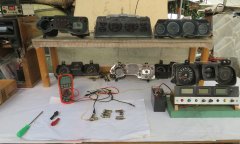
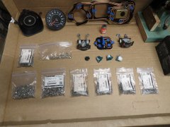 Layout of disassembled cluster. Note variety of stainless screws used in rebuild. Also note the Testors 'needle orange fluorescent' paint used to freshen up visibility of stock needles.
 -
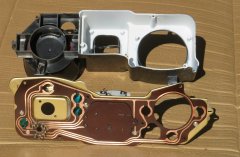 Back side of refurbished circuit board and view of pod interior with full white paint coating. The range of quality for factory painting here is surprising. I've had some with barely any coat with much exposed black plastic and others that were fairly well done. The flat/semi-gloss paint aids greatly in overall brightness. The dimmer is truly needed for night driving but allows for readability during daylight. To get uniform color and performance, if tack or clock is used, it should be opened and have the interior painted to match.
 -
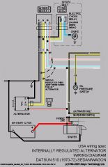
 Back side of rebuilt cluster on test bench. Note added integral lamp harness for factory clock or tachometer. Also note orange dots on lamp sockets with matching dots on PCB to aid in easy service for directional LEDs. Also note yellow tape on charge lamp. This used to indicate incandescent bulb used which is required for standard alternators to ensure adequate resistance to enable field coils to energize. The LED, being a diode, also does not allow bi-directional current flow, which is needed for correct charge state monitoring.
 -
Instrument-Cluster_Connector-Pin_Soldering.JPG
paolo commented on paolo's gallery image in Members Albums
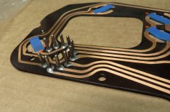 Circuit board gets stripped of stock green masking, cleaned, and re-coated with clear PCB mask coating. Note blue tape to protect bulb contact areas. Pins get a full sturdy silver solder filleting to ensure contact integrity and strengthening.
 -
Instrument-Cluster_Early-Bench-Testing.JPG
paolo commented on paolo's gallery image in Members Albums
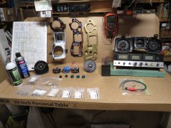
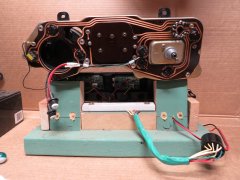
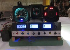 Early test of LEDs running at full dimmer brightness setting. Later balancing illumination, while tedious, proved very effective. Photos to come... Meters seen for fuel and temp on test bench cannot measure resistances when operating, thus the -1 reading. The toggle switch at right side disconnects harness wires to assess accurate POT settings. Shown are single turn pots which have been upgraded to 10-turn linear pots for easier and more accurate readings. The pots replace the thermistor and fuel level senders. The dimmer is a 10-Khz PWM dimmer activated by blue 'LIGHTS' knob Other push-button switches should be obvious.
 -
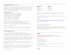
 As part of calibrating temp system, I analyzed several known good thermistors to generate reasonable Steinhart-Hart coefficients via curve matching of resistance measurements at various temps (e.g. 0'C, 20'C, 67'C, and 100'C). Results: RT=R25exp{B{(1/(T+273.15)-1/(25+273.15)} OHM where: R25=400, B=4100