paolo
-
Posts
118 -
Joined
-
Last visited
-
Days Won
1
1 Follower

paolo's Achievements
")


-
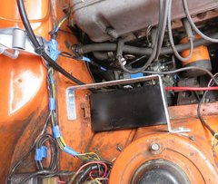
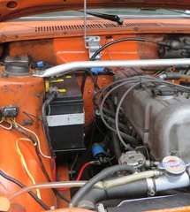
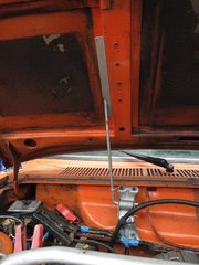 Photo of low profile hood support installed. Prop rod works similar to stock prop rod except you pull leftward to release rather than forward. Note raised aluminum front strut tower brace near photo bottom. See Front Strut-Tower Cross-brace
 -
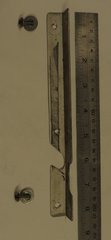 Photo of prototype with 4 years of use. Prop rod works similar to stock prop rod except you pull leftward to release rather than forward.
 -
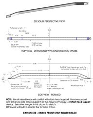
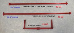
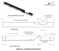 Aluminum angle used is cut from a Home Depot metals part (3/4" x 3/4" x 1/16" - 3-ft length). Can be constructed accurately enough using a hack saw, drill with bits, and a metal file. Suggest mounting with stainless screw & washers. The #8 pan-head sheet metal screws work well.
 -
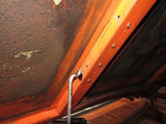 Prop rod may require slight bend outward (passenger side) to adjust tension against slide. Round end of rod (grind or file) where it touches guide to ensure smooth operation. Cut stock guide off using spot weld cutter. Remaining hubs seen protruding from brace in image. Smooth nubs and fill as preferred.
 -
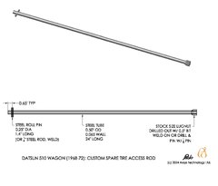
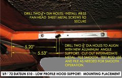 Install aluminum angle prop rod guide per dimensions in image. Placement shown sets hood raised angle at about 46.5 degrees from horizontal, slightly more than stock. Adjust placement laterally to accommodate preferred hood angle.
 -
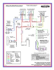
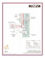
Various modifications or upgrades to the Datsun 510 Wagon (1968-1972 vintage). Some of these mods also apply to the Sedans.
-
-
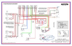
Useful DATA you can see for FREE!
-
-
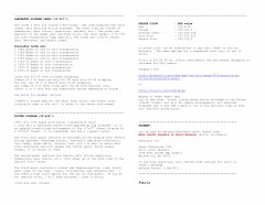
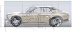
The New 510 overlay the Original 510
-
-
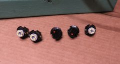
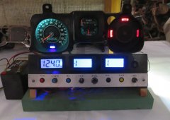
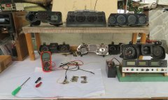
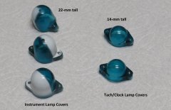 Image tells all. This explains why short profile 'bulbs' or LEDs are needed for the factory tachometer or clock.
 -
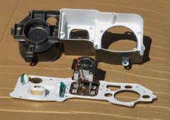
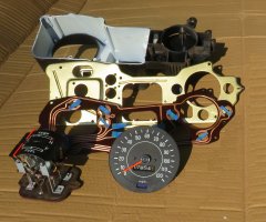
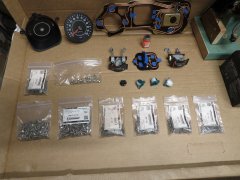
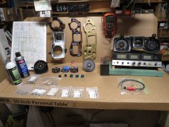
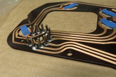
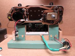
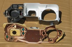
Images of various parts or states of my instrument cluster (dash pod) rebuilds and rebuilding processes.
-
-
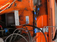
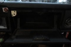
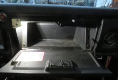 Installed and operating. Turns on when lights (markers+) are turned on and box door is opened. Intentionally not painted black as reminder for prototype model. Image taken near end of 'civil' twilight.
 -
A simple custom built glove box lamp made from readily available parts.
-
-
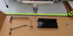
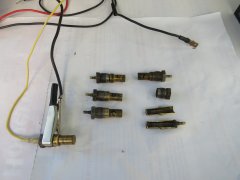
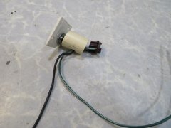
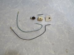 Glove box lamp parts. 1 - Outer frame (flat piece) from a a cut-out bit of 1/10" plastic of an old computer or electronic widget. 2- Pipe is cut from 3/4" CPVC pipe. 3 - Switch is a normally closed (NC) push-button available for cheap on-line by the 10-pack. 4 - Wires are color matched parts from an old harness with coordinated barrel connectors from VintageConnections.com 5 - LED another online Amazon part. 6 - Socket is typical lamp socket from Datsun 510 instrument cluster panel which fits snugly into pipe. All assembled with hot glue. Paint as desired. Contact me for part sources.
 -
'Exploded' assembly of parts (less bulb).
-
-
 paolo changed their profile photo
 -
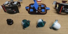
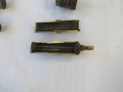 A sectioned Datsun thermistor, just in case you're curious as to how they are built.